Basic Buck Circuit
System Overview

To the right shows a system diagram and where the charge controller plays into the system.

SunCharger 2410
Above shows a more in depth look at the charge controller, which is outlined in the gray box. The solar panel, battery, and load (light bulb) are external and not included within the controller. Here are the steps to follow to understand better how the controller works.
-
From the solar panel a voltage and current reading is taken. which is necessary in determining when to charge.
-
When charging - the buck converter essentially reduces the voltage and keeps from overcharging the battery. (see below for more info). Not charging - circuit is in "off" state.
-
From the battery is a switching regulator, which acts like the buck converter and reduces the voltage from the 12 volt battery down to 5 volts. To supply the microcontroller with the necessary power required.
-
Another voltage sensor is taken from the battery to also determine when to charge the battery.
-
Also from the battery, before going out to the load, is a control switch to keep from draining the battery too much.
-
Another current sensor is in line with the load, so that the user is aware of how much power he or she is drawing.
-
Other
-
There is PWM signal sent to the buck converter based on readings from the battery and solar panel.
-
Led indicators to let the user know of what stage the controller is in.
-
LCD screen to display various parameters and one button to cycle through them. One other button to turn on the backlight for 10 seconds.
-
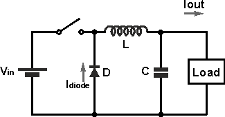
Above is a classic buck circuit configuration. In my controller, Vin is the solar panel, the switch is a P-MOSFET enhancement mode device, and the load is a battery. Same idea though. When the switch closes the inductor begins to charge up. When the switch opens, now the diode is active and the inductor switches polarity to keep current flowing into the battery. See figures a and b below for more detail.
Switched Mode Power Supply
Above, in the basic buck circuit diagram, is a switched mode power supply or SMPS. In a traditional power supply there is a step-down transformer, which is a bulky and expensive part of a power supply. Due to the low line frequency of 60Hz, it makes for larger components throughout, including capacitors and inductors. The power transistor is continuously on, which dissipates much power. Because of these factors combined, they are more bulky, more expensive, and less efficient. SMPS are improvements in all these areas by utilizing a technique called pulse-width modulation.
Below is a basic diagram of one.

Figure a shows a generic pulsed dc circuit using a MOSFET. The switch (MOSFET) is controlled by the pulse width modulator. R sub L is representing the load and V sub I is the input voltage.
If VI from figure a was set to 10 volts, assuming that this is an ideal circuit with no losses in the switch, and the output voltage seen across the load was 7.5 volts (figure b), we know that the duty cycle is set to 75%.
V out = d (duty cycle) x V in
and
t on (time period on) / T (one cycle) = d
7.5 = .75 x 10
and
150 / 200 = .75
Figure c shows another example but with the pulse width, duty cycle, at 50%.

The figure below shows the heart of the SunCharger 2410, however the pulse width modulator is the brains of the operation, continue on to find out what it is.


Micro-Controller
The board I use for the SunCharger 2410 is the Freedom KL25Z. Click on the PDF link to the side for the User's Manual. This puppy here controls it all! Under the schematics tab you will find an array of components being used as an add-on board to attach to the top of this board below. The freedom board will be used for led indicator lights, voltage sensor inputs, current sensor inputs, lcd display, interactive push-buttons, and most importantly a pin-header going to a separate board with the complete buck circuit design. Which will be pulse width modulating the MOSFET, controlling on and off to the load, picking up all the inputs mentioned, and getting power from the battery. Back on the add-on board will be another smaller SMPS (switching regulator) to reduce the 12 volts from the battery to 5 volts for the freedom board.

For more info click here or continue reading below.
Additionally the liquid crystal display below (2x32 characters) will be used to display all the user friendly parameters that one may want to be aware of. Included will be a button the user can hit to turn on the green backlight display for ease of viewing.